


How to Maintain a Perfect Hot Tub
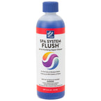
Achieve Clean, Clear Spa Water

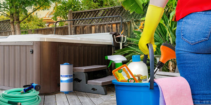
Maintain your Filters, Spa & Cover
DIY Spa Repairs & Wiring
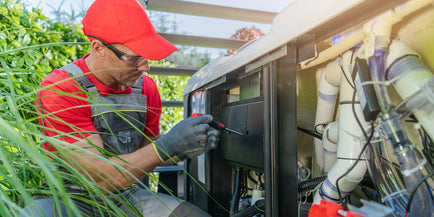
Get Free Expert Tech Support

Chat & Technical Support Request
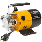
You may need

Your Recently Viewed Products: